

What Is a Hitachi 2.5-Inch Non-SATA HDD Board?
A Hitachi 2.5-inch Non-SATA HDD board is the electronic controller PCB installed on the underside of a legacy Hitachi Travelstar notebook hard drive. It communicates with the computer and controls the drive’s internal mechanical and electronic systems.
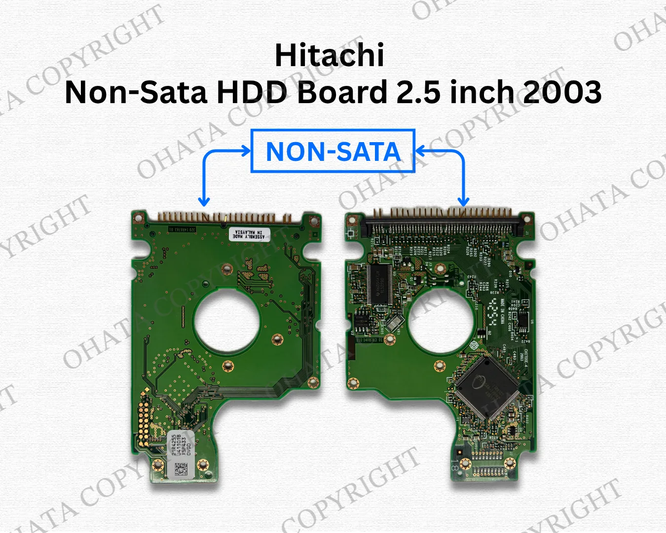
These boards use an IDE interface, also known as ATA or Parallel ATA. They predate the smaller Serial ATA connections used on later HDD SATA boards.
The controller board performs several important functions:
initializes the hard drive when power is applied
executes drive firmware
communicates with the host computer
starts and regulates the spindle motor
positions the actuator and read/write heads
manages cache or buffer memory
processes read and write operations
performs error detection and correction
monitors drive operation and SMART information
regulates and distributes electrical power
Although the board is much smaller than a desktop HDD controller board, it contains nearly all the electronics required to operate a mechanical notebook hard drive.
Within the HDD Board Classification, it belongs to the broad HDD Non-SATA Board family because it uses IDE/PATA rather than SATA.
The current purchasing category is more specific. It covers qualifying Hitachi 2.5-inch IDE/PATA controller boards from the applicable Travelstar generation. Current prices and conditions should be checked on the Hitachi Non-SATA HDD Board 2.5 inch 2003 buying page.
Learn more: How to Identify SATA and Non SATA HDD Boards
Hitachi Travelstar and the 2003 Generation
Travelstar was a major family of 2.5-inch hard drives designed for notebook and portable computers. These drives were developed for limited internal space and generally emphasized lower power consumption, reduced heat, quiet operation, compact dimensions, and resistance to movement or vibration.
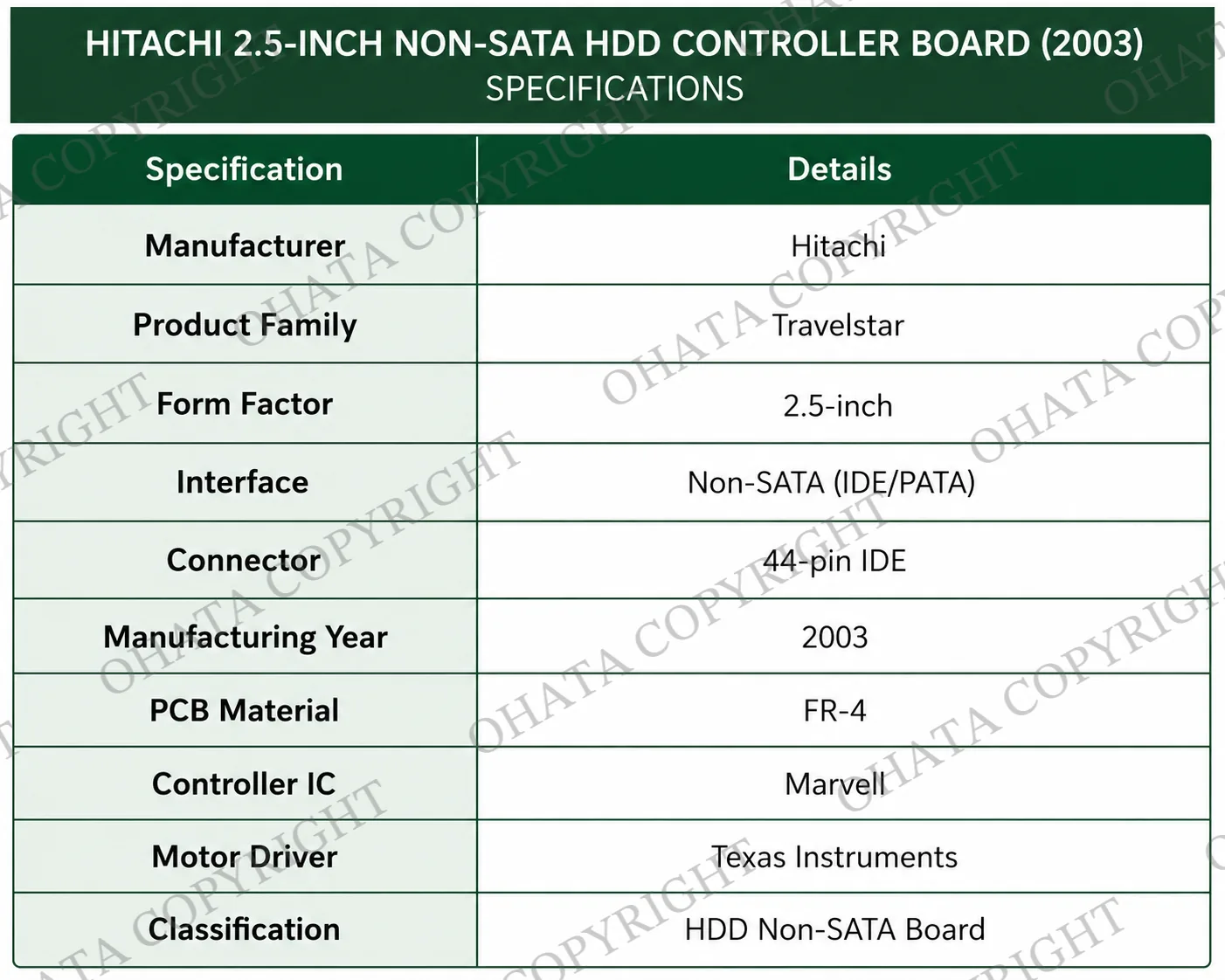
Travelstar hard drives appeared in notebook systems produced by companies such as:
IBM
Dell
Toshiba
HP
Compaq
Fujitsu Siemens
NEC
Sony
Panasonic
Acer
Early Travelstar models commonly used IDE/PATA. Later generations moved to SATA as notebook manufacturers adopted the newer interface.
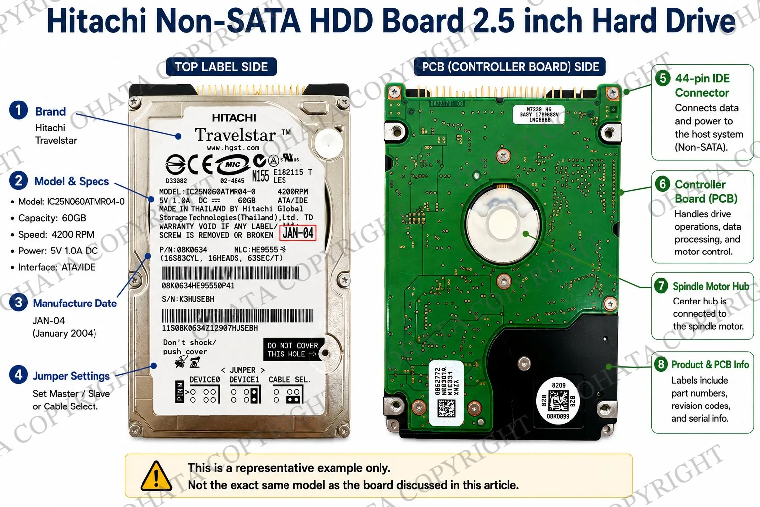
A significant change occurred in 2003 when Hitachi acquired IBM’s hard-drive operations and established Hitachi Global Storage Technologies, commonly known as HGST. As a result, some Hitachi and IBM-era Travelstar boards share aspects of their engineering, construction, or component layout.
This does not mean that every IBM, Hitachi, or HGST board belongs to the same purchasing category. The interface, form factor, manufacturer markings, production period, PCB design, and component configuration must still be examined.
Boards from around 2003 represent a transitional period in notebook storage:
IDE/PATA remained widely used.
SATA notebook drives were beginning to appear.
Solid-state drives were not yet common in consumer laptops.
Capacities from approximately 20 GB to 80 GB were common.
Spindle speeds of 4,200 or 5,400 RPM were typical.
Capacity and spindle speed can help identify the general period of a drive, but they do not determine the recycling category or buying value by themselves.
Why Notebook Drives Used IDE/PATA
IDE integrated the drive controller directly into the hard drive. Earlier storage systems often depended more heavily on separate controller hardware inside the computer. Moving controller functions onto the drive simplified computer design and installation.
Desktop IDE drives commonly used a 40-pin data connector together with a separate four-pin Molex power connection. Notebook drives required a smaller design, so the 2.5-inch version generally used one 44-pin connector carrying both data and power.
Feature
2.5-inch notebook IDE drive
3.5-inch desktop IDE drive
Typical PCB size
Compact
Larger
Data connection
44-pin IDE/PATA connector
40-pin IDE/PATA header
Power connection
Combined with the 44-pin interface
Separate Molex connector
Typical application
Notebook and portable computers
Desktop computers
Power requirements
Lower
Higher
Board interchangeability
Model-specific
Model-specific
Notebook and desktop IDE boards are not interchangeable. Their connectors, dimensions, firmware, power requirements, contact arrangements, and mechanical designs differ.
IDE offered broad compatibility, mature driver support, and relatively inexpensive implementation. Its limitations included a larger parallel interface, lower available transfer speeds, and increasingly difficult signal timing as performance improved.
SATA eventually replaced IDE by providing smaller connectors, serial communication, improved cable management, lower-voltage signaling, and higher available transfer rates.
How the Controller Board Operates
When power is supplied, the board reads its firmware and initializes the electronic systems required to operate the drive. It prepares the controller, spindle motor, actuator, read/write channel, cache memory, power circuitry, and IDE interface.
The motor driver accelerates the magnetic platters to the required speed and maintains stable rotation. It also controls the voice-coil actuator that moves the read/write heads across the platters. Continuous corrections keep the heads positioned over the intended data tracks.
The main controller translates IDE commands from the computer into physical operations performed by the drive. Common commands include read, write, seek, Identify Device, SMART, and cache-management operations. During reading and writing, specialized circuitry processes the small electrical signals travelling between the heads and the controller. The board checks data integrity, performs error correction, manages defective sectors, and transfers information between the drive and computer.
Firmware provides the operating instructions and calibration information required by the individual drive. Cache memory temporarily holds data during read and write operations to reduce delays caused by mechanical movement.These functions may be handled by separate components or integrated into fewer semiconductor packages, depending on the board revision.
How to Identify a Hitachi Travelstar IDE Board
Begin by confirming that the PCB was removed from a 2.5-inch mechanical notebook hard drive. Then inspect the connector, manufacturer markings, major integrated circuits, board outline, mounting holes, completeness, and condition.
Inspection point
What to examine
Original application
Controller board from a 2.5-inch mechanical notebook hard drive
Manufacturer
Hitachi, Travelstar, IBM, or HGST-related period markings
Interface
Compact 44-pin IDE/PATA connector
SATA connectors
Standard 7-pin data and 15-pin power pair should be absent
Main controller
Marvell or another period-appropriate controller IC
Motor driver
Texas Instruments or another compatible motor-control IC
Firmware
Separate ROM where used or firmware integrated into another device
Oscillator
Small metallic timing component near the controller circuitry
Internal contacts
Contacts for the spindle motor and read/write-head assembly
PCB shape
Compact outline designed for a 2.5-inch drive housing
Markings
Assembly number, revision, barcode, batch, and inspection codes
Condition
Missing parts, corrosion, burning, cracking, drilling, or contamination
The 44-pin connector is one of the strongest visual clues. However, it identifies the board as a notebook IDE/PATA design, not automatically as a specific Hitachi model or purchasing category.
A genuine factory board generally has precise component placement, uniform solder joints, clear silkscreen printing, consistent solder mask, and professionally manufactured traces. Evidence of repaired traces, replaced chips, removed firmware devices, or harvested components may indicate modification.
Complete counterfeit HDD controller boards are less common than counterfeit consumer accessories. However, aftermarket replacement boards, repaired boards, and boards modified for data recovery may be encountered.
Manufacturer and PCB numbers are useful identification aids, but no single marking should be used alone.
Controller Board Construction and Components
The PCB is generally manufactured from FR-4 fiberglass-reinforced epoxy laminate. Multiple copper layers provide signal routing, grounding, power distribution, and connections between components.
The exterior normally contains a protective solder mask, printed component references, plated holes, mounting points, internal drive contacts, and surface-mounted electronic components.
Component
Primary function
Identification clues
Main controller IC
Manages IDE communication, firmware execution, cache operation, data processing, error correction, defect management, and drive monitoring
Usually one of the largest square or rectangular ICs near the center of the PCB
Motor-driver IC
Controls spindle rotation, actuator movement, power sequencing, current, and motor protection
Commonly positioned near the internal motor contacts and wider copper pathways
ROM or firmware memory
Stores startup instructions, calibration values, adaptive information, and hardware configuration
Often a small eight-pin device near the controller when separately installed
Cache memory
Temporarily stores information during read and write operations
Normally positioned near the main controller
Crystal oscillator
Provides an accurate timing reference for board operations
Small metallic package near the controller circuitry
Read/write channel circuitry
Amplifies and processes signals travelling between the magnetic heads and controller
Integrated into the controller or positioned near the internal head contacts
Voltage-regulation circuitry
Converts and stabilizes incoming electrical power
Includes regulators, MOSFETs, inductors, capacitors, and protection devices
Passive components
Provide filtering, timing, voltage stabilization, current control, and noise reduction
Numerous small resistors, capacitors, ferrite beads, and diodes
IDE connector
Carries data and power between the hard drive and notebook
Compact 44-pin connector along the board edge
Internal drive contacts
Connect the PCB to the spindle motor and head assembly
Plated contact areas positioned to align with the drive mechanism
Many boards from this generation use a Marvell controller IC, but component suppliers vary between production runs. Marvell controllers were used for ATA command processing, logical block addressing, cache management, error correction, defect management, firmware execution, power management, and drive-health monitoring.
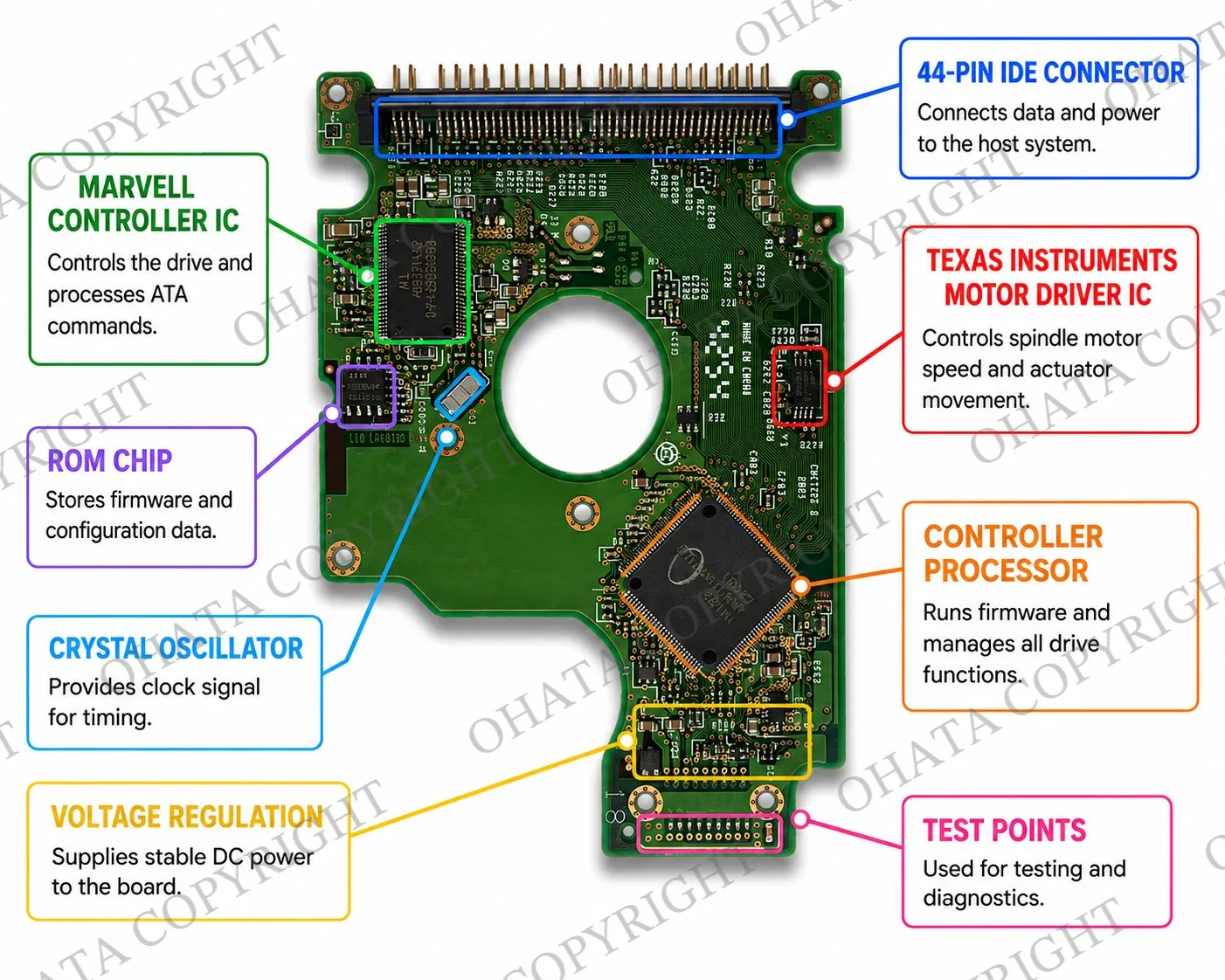
Texas Instruments motor-driver ICs are also common on some boards from this period. Other component manufacturers may appear on different Hitachi revisions.
The motor driver supplies and controls the current required for spindle rotation and actuator movement. Because it handles more current than many logic components, it is often connected to wider copper pathways and placed near power circuitry.
The ROM chip, when separately installed, may contain calibration and adaptive information associated with the original mechanical drive. Moving a controller board between drives does not necessarily restore operation, even when the board shape and connector appear identical.

Some designs integrate firmware into the main controller or another memory component. The absence of a separate ROM package does not automatically mean that the board is incomplete.
The crystal oscillator supplies timing signals used for firmware execution, IDE communication, cache timing, servo calculations, and motor synchronization.
Smaller components remain essential to board operation. Ceramic capacitors stabilize and filter voltages. Resistors control current and condition signals. Ferrite beads reduce high-frequency interference. Regulators and protection devices help provide suitable power to the controller, memory, analog circuitry, and motor driver.
Board Numbers and Manufacturing Codes
Hitachi controller boards may contain several printed, engraved, or labelled codes. These can include:
PCB assembly number
board revision
production batch
factory identifier
barcode
inspection marking
firmware-related code
date or manufacturing code
A PCB number normally identifies the controller-board design or assembly revision. It does not always identify the complete hard-drive model.
Different drive capacities may use similar controller layouts, while visually similar boards may contain different firmware or adaptive information. When identifying a board for repair, the PCB markings should be considered together with the complete drive label and firmware requirements.
For recycling classification, the markings support identification but do not replace examination of the manufacturer, form factor, interface, component layout, completeness, and condition.
SATA and Non-SATA Notebook Boards
The connector is the clearest initial difference between IDE/PATA and SATA notebook HDD boards.
Feature
Hitachi 2.5-inch IDE/PATA board
SATA notebook HDD board
Interface
Parallel ATA
Serial ATA
Main connector
One compact 44-pin connector
Separate 7-pin data and 15-pin power connectors
Typical period
Common before and during the early SATA transition
Common from the mid-2000s onward
Data and power
Combined in the notebook connector
Carried through separate connections
Signalling
Parallel
Serial
Board design
Legacy controller architecture
Later, often more highly integrated architecture
Broad HDD category
HDD Non-SATA Board
HDD SATA Board
IDE and SATA controller boards are physically and electronically different. They cannot be interchanged simply because they came from similar-sized notebook hard drives.
A notebook board should not be classified as SATA based only on its age or size. Many laptops produced before approximately 2005 used IDE/PATA drives.
Learn more in the HDD SATA Board Scrap Guide, the general HDD Non-SATA Board Guide, and the HDD SATA and Non-SATA Classification Guide.
Common Identification Mistakes
Several assumptions can lead to incorrect identification:
All notebook HDD boards are SATA: Notebook drives used IDE/PATA for many years before SATA became standard.
The PCB number identifies the complete drive: A number may identify only the board design or revision. The drive label and firmware information may be needed for exact model identification.
All Hitachi boards use identical controllers: Component suppliers, firmware arrangements, layouts, and board revisions changed over time.
A Marvell controller proves that the board is Hitachi: Marvell supplied controller technology to multiple storage manufacturers.
Every board without a separate ROM is incomplete: Some designs integrate firmware functions into another component.
Desktop and notebook IDE boards are interchangeable: Their connectors, power arrangements, dimensions, firmware, and mechanical designs differ.
Every Hitachi Travelstar board belongs to this purchasing category: Different interfaces, sizes, periods, and board designs may have different classifications.
Accurate identification should use several features together, including the manufacturer, form factor, connector, PCB outline, mounting holes, component placement, internal contacts, markings, completeness, and condition.
Where These Boards Are Found
Hitachi Travelstar IDE boards can still be recovered from:
obsolete notebook computers
corporate computer replacements
repair shops
electronics dismantling operations
IT asset disposition programs
data-destruction projects
warehouse liquidations
educational collections
vintage-computer equipment
industrial systems that retained older notebook drives
Large quantities may come from organizations replacing legacy computers or storage systems with newer SATA drives or solid-state storage.
Recoverable Materials and Recycling Value
Hitachi IDE controller boards contain recoverable electronic material within a small, component-dense PCB.
Copper commonly represents a substantial portion of the recoverable metal. It is present in surface traces, internal PCB layers, ground planes, power-distribution areas, plated holes, contact pads, and component leads.
Gold may be present as a thin finish on selected connector contacts, internal drive contacts, test pads, and certain component structures. The visible quantity is small and should not be treated as proof of a particular precious-metal yield.
Tin is commonly associated with solder. Nickel may be used beneath plated finishes or within component structures. Silver may occur in some solder alloys or electronic components.
Other materials may include aluminum, iron, silicon-based semiconductor material, fiberglass, resin, and specialty alloys.
Material
Possible locations
Copper
PCB traces, internal layers, ground planes, plated holes, contacts, and component leads
Gold
Selected connector contacts, internal contacts, test pads, and some component structures
Tin
Solder joining components to the PCB
Nickel
Beneath plated finishes and within selected electronic structures
Silver
Certain solder alloys and electronic components
Aluminum
Limited component or mechanical structures
Silicon
Controller, motor-driver, memory, and firmware devices
Fiberglass and resin
Structural FR-4 PCB substrate
A photograph cannot determine internal copper weight, plating thickness, bonding-wire composition, solder formulation, precise precious-metal content, or exact material-recovery yield.
Professional recycling may involve mechanical preparation, material separation, controlled smelting, hydrometallurgical processing, or other specialized refining methods. Separating the PCB from the drive housing allows its electronic fraction to be processed independently from the aluminum, steel, platters, magnets, motors, and other mechanical materials.
Do not burn boards, scrape contacts, cut plated areas, grind components, or apply chemicals to test for precious metals. These actions can reduce recoverable value and create fire, dust, chemical, and environmental hazards.
Complete, Incomplete, and Damaged Boards
A complete Hitachi controller board retains its original PCB structure and the components installed by the manufacturer. Depending on the original design, these may include the controller IC, motor-driver IC, firmware device, cache memory, crystal oscillator, 44-pin connector, internal contacts, power circuitry, and passive components.
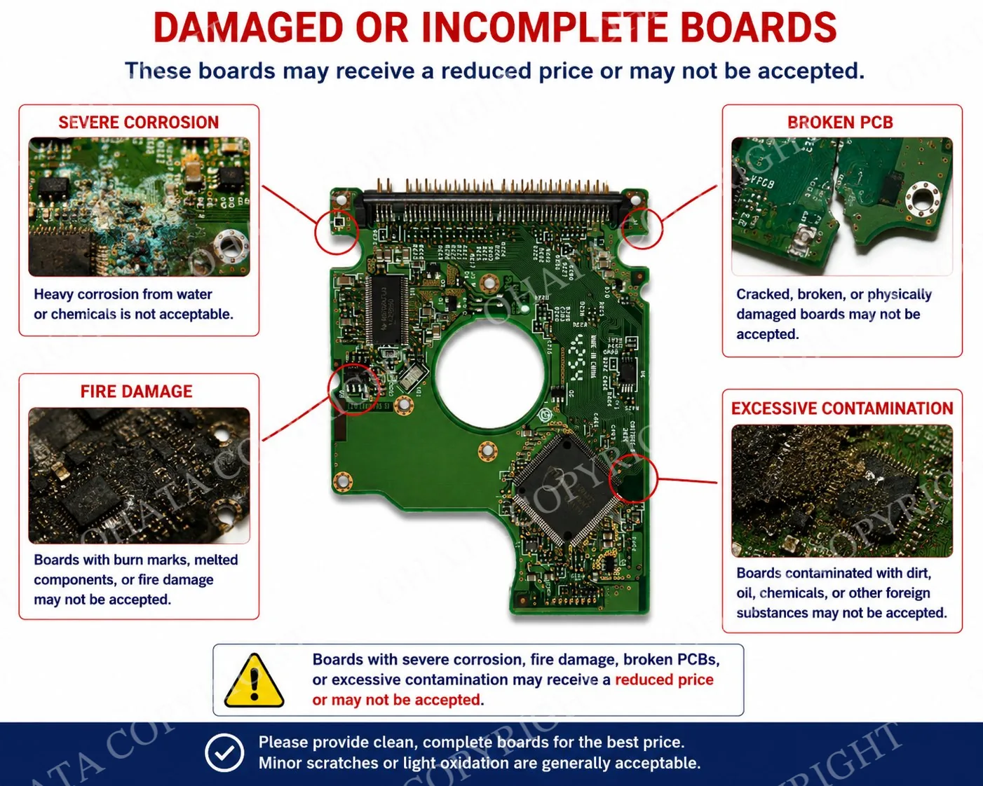
An incomplete board may have missing integrated circuits, a detached connector, removed firmware components, broken internal contacts, cut sections, drilled holes, cracks, or extensive component harvesting.
Not every board contains an identical component arrangement. Completeness should be judged against the original design of the specific board rather than another Hitachi model.
Condition | Typical characteristics |
|---|---|
Clean and complete | Original components present, intact PCB, readable markings, and minimal contamination |
Ordinary used condition | Light scratches, normal aging, minor discoloration, or limited surface oxidation |
Moderately damaged | Light corrosion, small edge damage, minor contamination, or limited connector damage |
Severely damaged | Broken PCB, missing ICs, drilled sections, heavy corrosion, burning, chemical exposure, or extensive contamination |
Minor dust, ordinary surface wear, light scratches, or normal aging do not automatically prevent classification when the board remains identifiable and substantially complete.
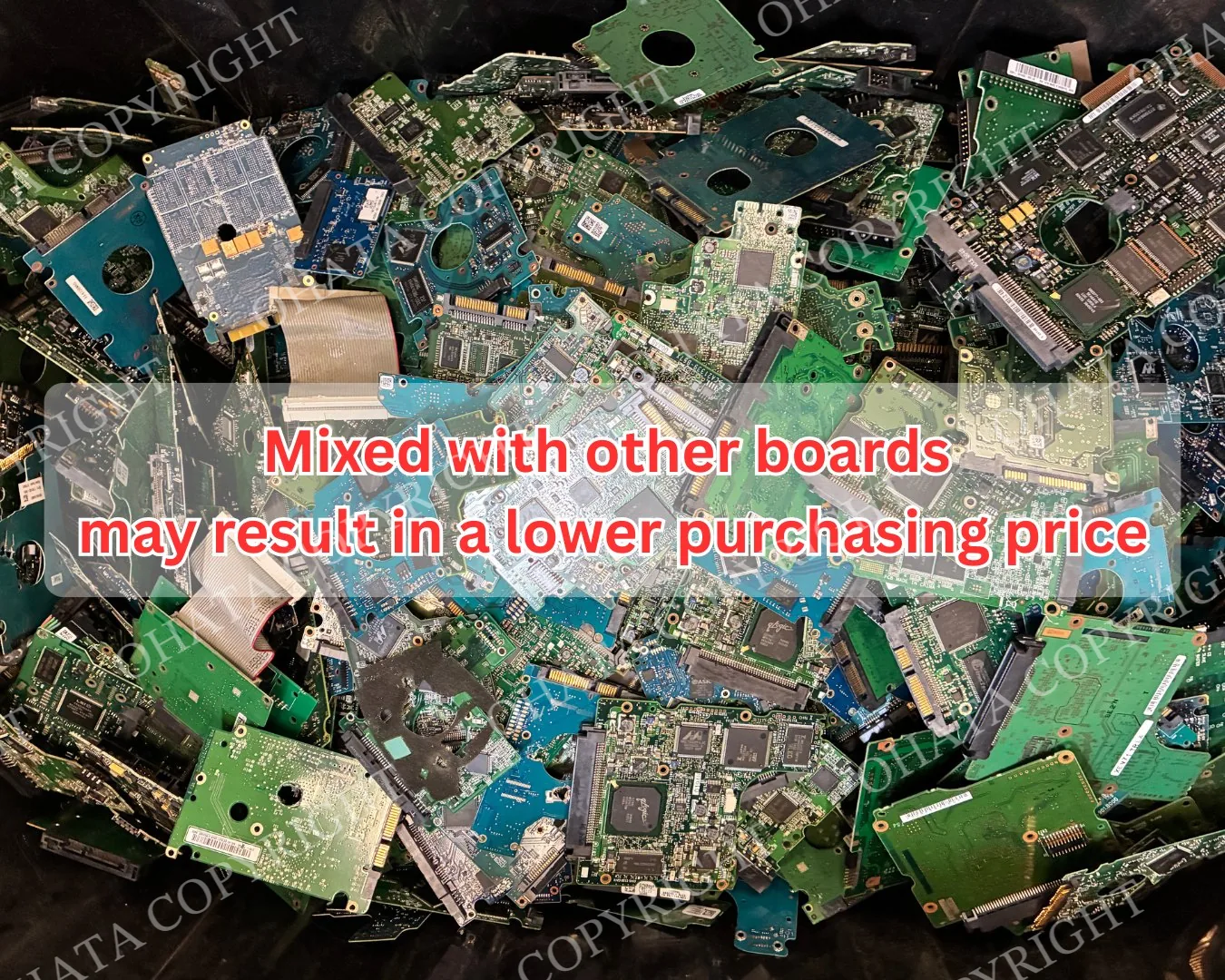
Broken connectors, missing controller or motor-driver ICs, removed firmware devices, cracked fiberglass, fire damage, water exposure, heavy corrosion, drilling, and severe contamination may reduce purchasing value or result in rejection.
Sorting, Data Security, and Buying Guidelines
The PCB is normally attached to the underside of the hard drive with small Torx screws. Remove it carefully without cracking the board, damaging the internal contacts, or pulling off components.
The metal housing, platters, magnets, spindle motor, screws, and other mechanical parts are not part of the loose controller-board category. Complete hard drives should be checked against the appropriate hard-drive buying categories.
Keep Hitachi 2.5-inch IDE controller boards separate from:
desktop IDE controller boards
SSD controller boards
optical-drive controller boards
USB bridge boards
laptop logic boards
complete hard drives
loose platters and mechanical parts
unrelated circuit boards
heavily contaminated material
The controller board generally does not contain the user’s normal documents or files. Those remain stored magnetically on the platters. However, a separate ROM or firmware component may contain drive-specific operating and calibration information.
Removing the controller PCB does not erase or securely destroy information stored on the hard drive. Data-bearing equipment should be handled according to the owner’s security, privacy, retention, and destruction requirements before it leaves their control.
The current purchasing category covers qualifying genuine Hitachi 2.5-inch IDE/PATA boards from the applicable Travelstar generation. Purchases start at 1 lb according to the current buying page.
Brand, storage capacity, spindle speed, operating condition, and original purchase price do not determine the buying value by themselves. Evaluation considers:
manufacturer and product family
2.5-inch form factor
IDE/PATA interface
approximate production period
PCB construction
original component population
completeness
physical condition
contamination
quantity
current electronic-scrap market
AI-Assisted Recognition and Classification
AI-assisted image analysis may help identify a possible Hitachi Travelstar IDE controller board from visible features in a photograph.
Visual feature
How it supports identification
Connector
A 44-pin connector supports identification as a 2.5-inch IDE/PATA board
Board dimensions
The compact PCB matches the form factor of a notebook hard drive
PCB outline
The shape may correspond with a particular Travelstar drive family
Controller placement
Many boards position the main controller near the central area
Motor-driver position
Often located near the spindle contacts and power circuitry
Mounting holes
Their arrangement corresponds with the mechanical drive housing
Internal contacts
Contact placement helps confirm that the PCB controlled a mechanical HDD
Silkscreen markings
Board numbers, inspection codes, and revisions provide supporting evidence
Manufacturer labels
Hitachi, Travelstar, IBM, or HGST markings may help identify the board family
Physical condition
Missing chips, cracks, corrosion, and burning may be visible in photographs
Clear photographs of both sides provide better preliminary evidence than a single angled image. Labels and board markings should be readable, and the connector edge should not be hidden.
AI recognition should consider several features together. A 44-pin connector may identify a notebook IDE board, but it does not establish the manufacturer or exact purchasing category by itself. Likewise, a Marvell or Texas Instruments chip may appear on boards from different manufacturers.
Preliminary image recognition cannot confirm hidden PCB layers, firmware contents, exact manufacturing history, internal material composition, or final purchasing value.
The HDD Board Classification is an internal educational and purchasing reference. It uses SATA and non-SATA as broad interface families while allowing current price pages to establish more specific categories by manufacturer, form factor, design, or production period.
It is not an international standard, government specification, manufacturer repair standard, computer-performance rating, or universal electronic-scrap grade.
Final classification, acceptance, and purchasing value are confirmed after inspection under current buying requirements.