

What Is an HDD Controller Board?
An HDD controller board is the printed circuit board attached to the underside of a mechanical hard disk drive. It may also be called an HDD PCB, hard-drive logic board, or hard-drive circuit board.
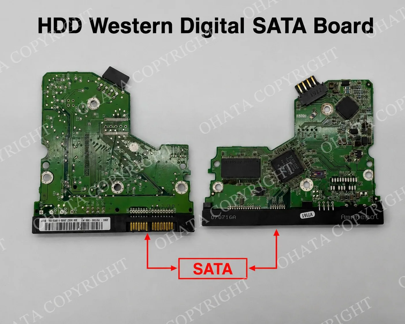
The controller board manages communication between the hard drive and the computer. It also controls the spindle motor that rotates the magnetic platters, positions the read/write heads, executes firmware, manages cache memory, regulates electrical power, monitors drive operation, and performs error detection and correction.
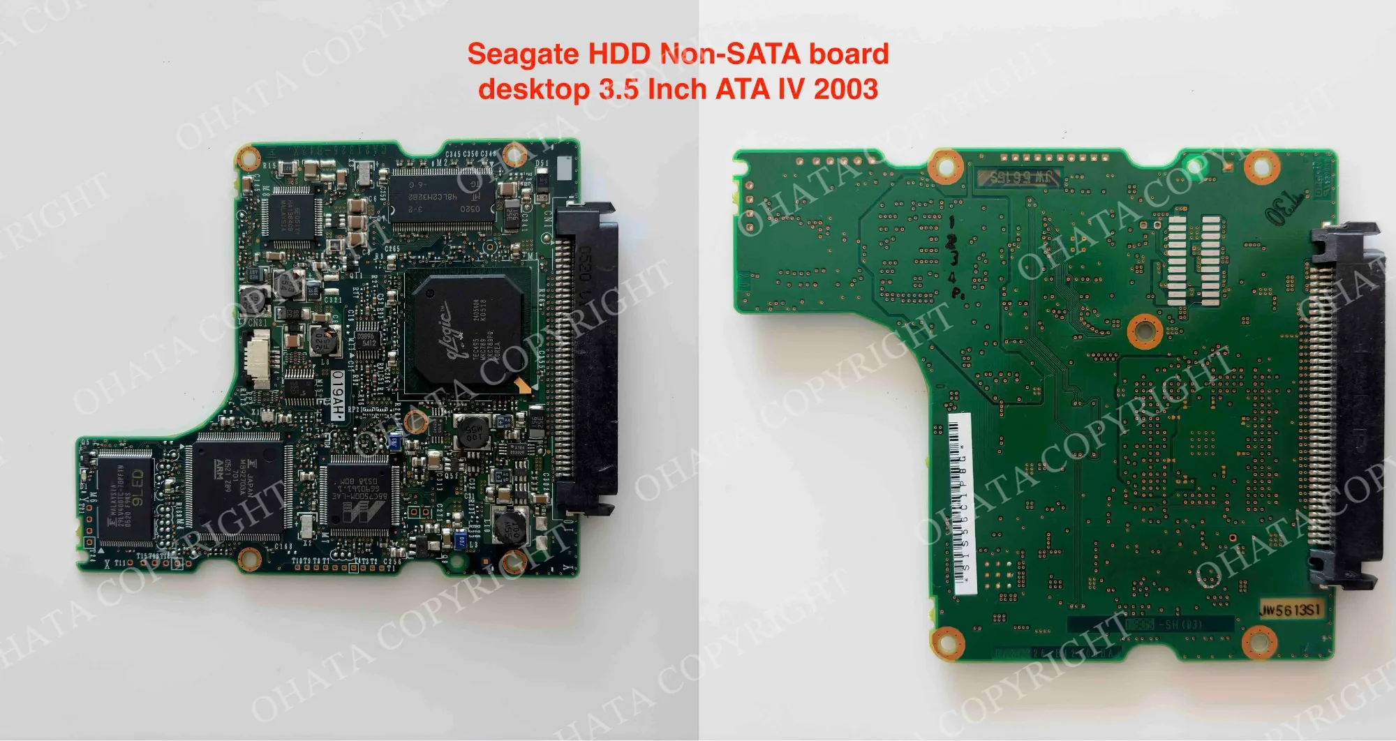
Although manufacturers use different PCB shapes and component arrangements, most HDD controller boards contain the same general systems: a main controller, motor-control circuitry, firmware storage, cache memory where required, voltage-regulation components, interface connectors, and contacts leading to the internal drive mechanism.
The controller board is only one part of the complete hard drive. User files are normally stored magnetically on the platters inside the drive enclosure, not on the controller PCB. The board may still contain firmware and calibration information required for the drive to operate.
Within the Ohata HDD Board Classification, controller boards are first separated into two primary groups:
These are broad interface groups. Current purchasing categories may divide the boards further according to manufacturer, drive size, production period, PCB design, components, completeness, and condition.
The interface provides the first classification step, but it does not necessarily determine the final item-specific buying category or price.
Learn more: How to Identify SATA and Non SATA HDD Boards
History of HDD Controller Boards
Early hard drives used controller electronics installed separately from the drive mechanism. During the 1980s and early 1990s, manufacturers increasingly integrated these functions onto a PCB mounted directly beneath the drive.
Several interfaces appeared during this period, including ST-506, ESDI, SCSI, IDE, ATA, and EIDE. IDE, later standardized as Parallel ATA or PATA, became especially common in personal computers. These drives generally used a wide ribbon cable connected to a large parallel pin header.
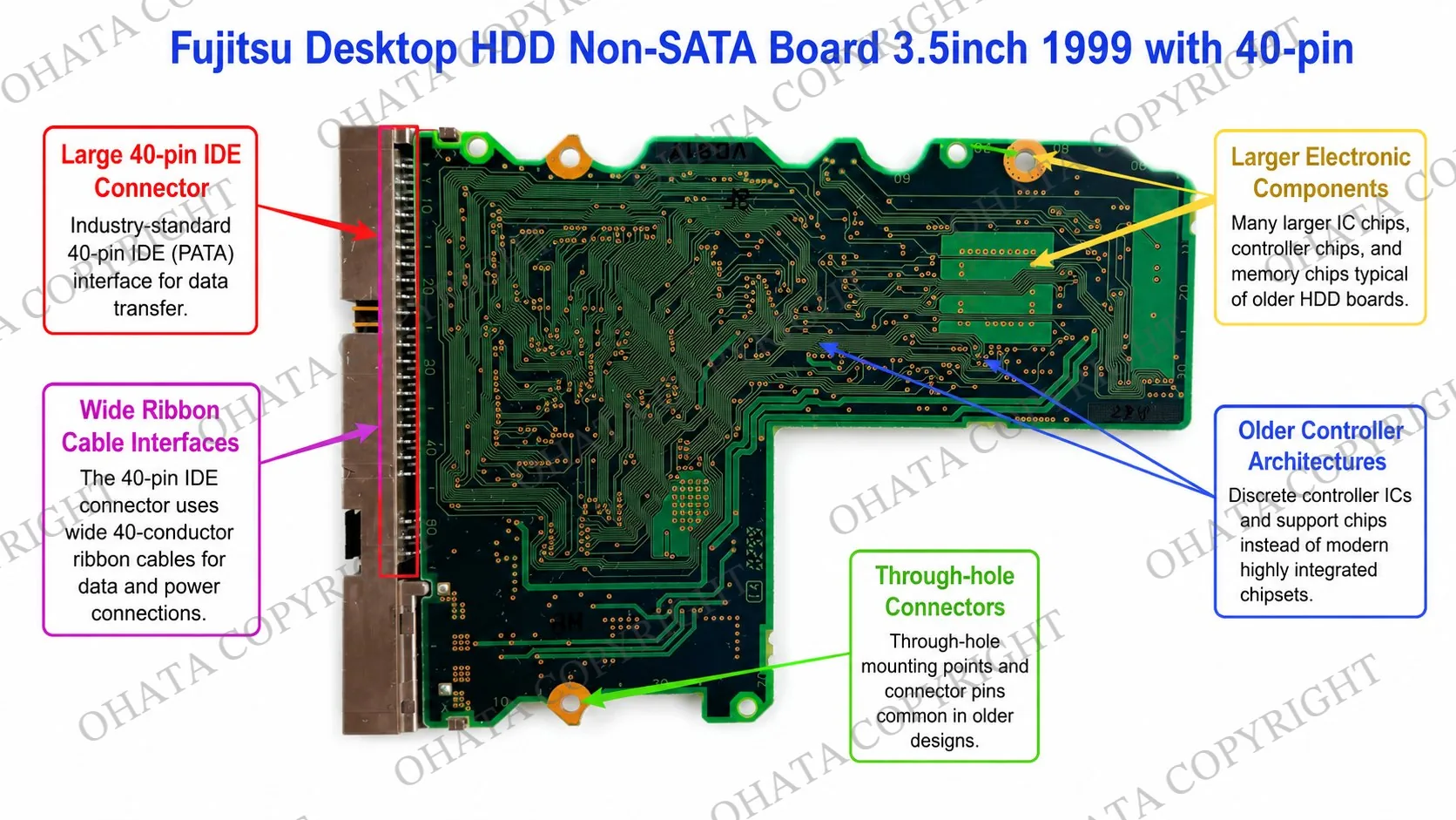
As semiconductor manufacturing improved, controller boards became smaller and more integrated. Functions previously handled by several chips were combined within fewer packages. Manufacturers also introduced larger cache memory, more advanced motor drivers, embedded firmware, improved error correction, and more efficient power regulation.
Serial ATA was introduced in the early 2000s and gradually replaced IDE and PATA in consumer computers. SATA used smaller serial connectors, simplified cable design, reduced interference, improved airflow within computer cases, and supported higher transfer speeds.
The major SATA generations support nominal interface speeds of:
SATA I: 1.5 Gb/s
SATA II: 3.0 Gb/s
SATA III: 6.0 Gb/s
SATA became common in desktop computers, laptops, servers, external storage, surveillance systems, and network-attached storage. IDE, ATA, EIDE, SCSI, and other non-SATA boards remain present in recycling streams as older computers, servers, workstations, industrial equipment, and embedded systems are retired.
Interface generation describes how a drive communicates. It does not determine recycling value by itself.
HDD SATA and Non-SATA Classification
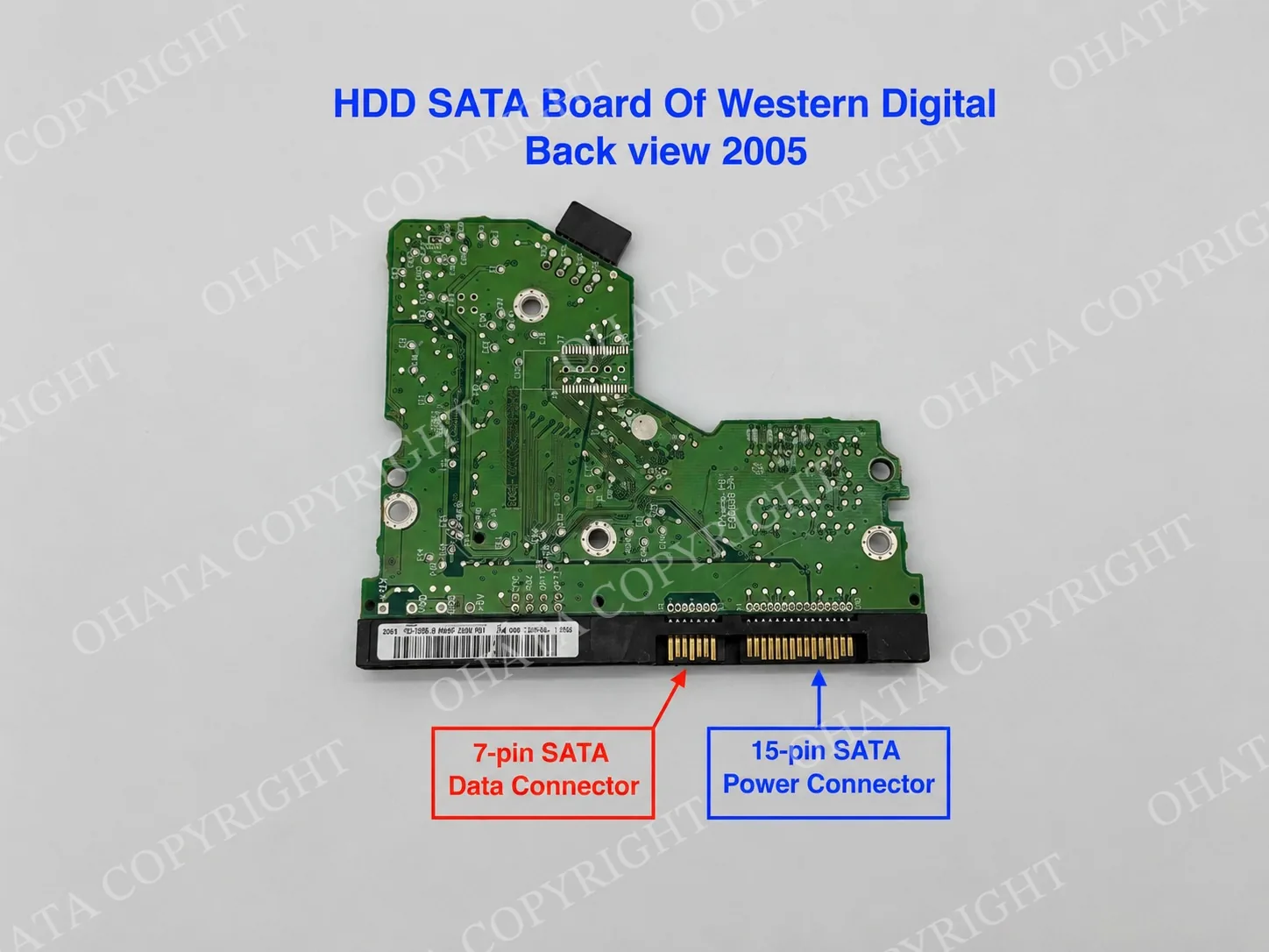
An HDD SATA board is the controller PCB from a mechanical hard drive using the Serial ATA interface. Its clearest feature is a pair of adjacent, keyed connectors: a 7-pin SATA data connection and a 15-pin SATA power connection.
SATA boards generally have compact layouts, densely installed surface-mounted components, modern controller processors, motor-driver circuitry, firmware storage, cache memory where required, and small internal contacts. They commonly appear on drives produced from the early 2000s onward.
SATA boards can be recovered from 2.5-inch laptop drives, 3.5-inch desktop drives, external hard drives, NAS equipment, servers, surveillance recorders, industrial computers, and gaming systems.
An HDD non-SATA board is a controller PCB from a mechanical drive using IDE, PATA, ATA, EIDE, SCSI, or another legacy or proprietary interface. These boards often use wide pin headers, ribbon-cable connections, jumper blocks, Molex power connections, or specialized enterprise connectors instead of the standard SATA connector pair.
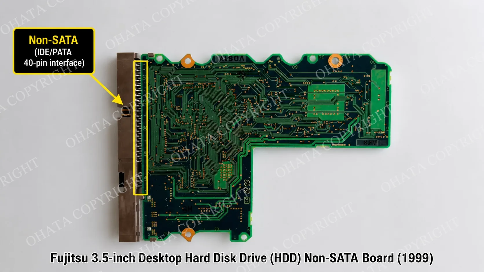
IDE and PATA boards commonly have a 40-pin data header, although the exact connector depends on the drive form factor. Many also include a four-pin Molex power connector and a jumper block used for drive configuration.
ATA standardized the interface commonly associated with IDE. EIDE expanded its capabilities while retaining a similar physical connector arrangement. Because these designs are closely related, their controller boards remain within the broader non-SATA group.
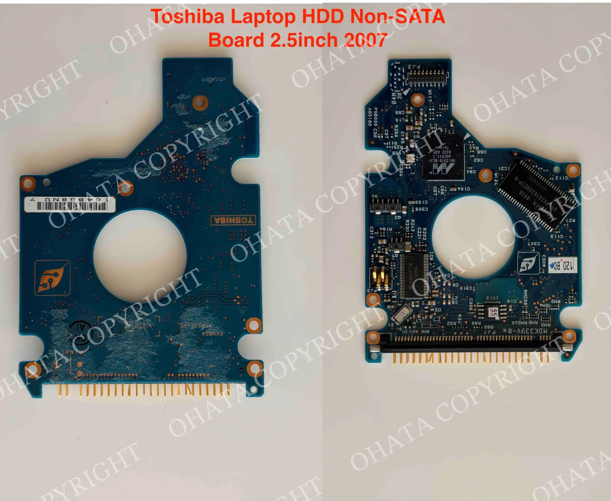
SCSI drives were widely used in servers, engineering workstations, and industrial systems. Their boards may contain high-density interface connectors, controller processors, cache memory, firmware devices, motor drivers, and substantial power-regulation circuitry.
SAS should not automatically be grouped with SATA because it is a separate enterprise storage interface, even though some SAS connectors resemble SATA. SAS and other specialized drive boards should be evaluated under their applicable purchasing category.
A narrow SATA connector pair indicates the SATA group. A legacy pin header, ribbon-cable interface, or specialized non-SATA connector indicates the non-SATA group.
How to Identify an HDD Controller Board
Begin by confirming that the PCB came from a mechanical hard drive. HDD boards have an irregular outline designed to fit the underside of a drive and normally include mounting holes, a host interface, and contacts connecting the board to the spindle motor and read/write head assembly.
Next, examine the interface and the complete board:
Inspection point
HDD SATA board
HDD non-SATA board
Data connection
Narrow 7-pin SATA connector
IDE, PATA, ATA, EIDE, SCSI, or another legacy connector
Power connection
15-pin SATA power connector
Often a Molex connector or interface-specific power connection
Connector layout
Two adjacent keyed connectors
Wide pin header, ribbon-cable connection, or specialized connector
Jumper block
Usually absent
Common on many IDE and PATA drives
PCB design
Generally compact and densely populated
Often larger with wider component spacing
Components
Controller, motor driver, firmware, cache, and power circuitry
Similar functions using an older layout and component generation
Internal contacts
Motor and read/write head contacts
Motor and read/write head contacts
Typical period
Common from the early 2000s onward
Common before widespread SATA adoption
Component density and board size can support identification, but they are not universal rules. Some late non-SATA boards are compact, while certain SATA boards may have relatively open layouts.
Manufacturer names, part numbers, date codes, firmware labels, and PCB revision markings can provide useful confirmation. They should not replace examination of the interface and complete board construction.
Inspect both sides. The component side normally contains the main ICs and host connectors. The reverse may show internal drive contacts, test points, grounding areas, revision codes, manufacturing marks, solder joints, or damage that is not visible from the front.
The host interface remains the fastest identification feature, but classification should also consider the PCB outline, motor contacts, installed components, original application, completeness, and condition.
Components and PCB Construction
Most HDD controller boards use multilayer fiberglass-reinforced epoxy laminate, commonly called FR-4. Copper within the PCB provides signal routes, grounding, power distribution, contact areas, and plated connections between layers.
The exterior normally has a protective solder mask, printed component markings, mounting holes, contact pads, and surface-mounted components. Green is common, but boards may also use black, blue, brown, or another solder-mask color. Board color does not determine the classification.
The main controller IC acts as the primary processor. It manages host communication, firmware execution, data processing, error correction, cache control, drive initialization, internal diagnostics, SMART monitoring, and read/write operations. It is commonly one of the largest square or rectangular packages on the board.
Cache memory temporarily stores data during read and write operations. Older boards may contain only a small amount, while newer consumer and enterprise drives may have much larger buffers. Cache capacity affects drive performance but does not determine the recycling category.
The motor-driver IC controls platter rotation and movement of the actuator arm. It starts and regulates the spindle motor, positions the read/write heads, and manages acceleration and braking. Because it handles substantial electrical current, it may be located near the internal motor contacts and connected through wider copper pathways.
Firmware initializes the drive and controls its internal operation. It can include model-specific settings, factory calibration values, adaptive parameters, and startup instructions. Some boards use a separate ROM or flash-memory package, while others integrate these functions into the main controller.
The absence of a separate firmware chip does not automatically mean that a component has been removed. The expected design must be confirmed for the particular board.
Voltage-regulation circuitry converts incoming power into the stable voltages required by the controller, motor driver, memory, and other components. This area may contain MOSFETs, voltage regulators, capacitors, inductors, protection diodes, filters, and current-sensing components.
Smaller resistors, capacitors, oscillators, ferrite beads, and filters support timing, signal stability, power filtering, and electrical protection.
The board also has contacts connecting it to the spindle motor and read/write head assembly. These often align with spring contacts when the PCB is secured to the drive. Missing, cut, damaged, or heavily corroded contact areas may affect completeness and evaluation.
Manufacturers, Sources, and Similar Boards
Western Digital, Seagate, Toshiba, Hitachi or HGST, Samsung, Fujitsu, IBM, Quantum, and Maxtor have produced mechanical hard drives with a wide range of controller-board designs.
Western Digital and Seagate boards are common in desktop, laptop, external, enterprise, NAS, and surveillance applications. Toshiba and Fujitsu produced many compact laptop and specialized drives. Hitachi and HGST supplied consumer and enterprise storage products.
Samsung manufactured mechanical SATA drives before shifting its storage focus primarily toward solid-state products. IBM developed consumer and enterprise drive families before transferring its HDD business to Hitachi. Quantum and Maxtor produced many recognizable IDE, ATA, and SCSI drives during the 1990s and early 2000s.
A manufacturer may use several PCB layouts during the same production period. Two boards with the same brand can differ in interface, form factor, controller design, component population, and applicable purchasing category.
HDD controller boards are sometimes confused with other small PCBs. Common examples include:
SSD boards: Contain NAND flash-memory packages and do not control a spindle motor or mechanical read/write heads.
USB bridge boards: Convert SATA communication to USB inside an external-drive enclosure but are separate from the controller PCB attached to the HDD.
Optical-drive boards: Control CD, DVD, or Blu-ray mechanisms and use different motor and connector arrangements.
Laptop motherboards: Contain the computer’s processor, memory connections, display interfaces, external ports, and broader system circuitry.
Industrial control boards: May contain relays, transformers, terminal connections, or power devices unrelated to hard-drive operation.
SAS boards: Use a separate enterprise interface and require classification under the applicable category.
Correct identification depends on recognizing the combination of the drive interface, controller IC, motor-driver circuitry, firmware section, internal contacts, mounting pattern, and PCB shape.
Buying Conditions and Value Factors
Purchases of qualifying HDD controller-board scrap start at 1 lb. Boards do not generally need to work because purchasing evaluation is based on physical construction and recoverable material rather than stored data or electronic performance.
For the best evaluation, a board should retain its complete original PCB, controller IC, motor driver, cache memory where originally installed, firmware component where applicable, voltage-regulation circuitry, interface connectors, internal contacts, and other major factory-installed components.Complete boards are easier to identify and generally retain more recoverable electronic material than stripped or fragmented boards. Component density, PCB construction, retained contacts, contamination, physical condition, and processing requirements may all affect the purchasing evaluation.
Brand, storage capacity, rotational speed, interface speed, firmware version, working condition, resale value, and original purchase price do not determine the category by themselves. Boards should be kept dry and reasonably clean. Separate SATA boards from non-SATA boards, SAS boards, SSD boards, USB bridge boards, optical-drive boards, complete hard drives, batteries, wires, plastic, loose metal, and unrelated circuit boards.
Further sorting by manufacturer, drive size, board design, production period, or purchasing category may be required. A Western Digital SATA board and a Seagate SATA board share an interface group but may not qualify for the same item-specific buying category. Normal labels, light dust, minor surface wear, and ordinary handling marks may be acceptable when the board remains substantially complete and identifiable.
Missing controller ICs, motor drivers, cache memory, firmware devices, connectors, contacts, or PCB sections may lower the classification or purchasing value. Cracks, drilled holes, broken corners, damaged mounting areas, extensive rework, and component harvesting can also affect evaluation.
Corrosion, oxidation, mold, water damage, overheating, burning, carbonization, oil, adhesive, paint, chemicals, and other contamination may require separate inspection. Severely burned, chemically treated, hazardous, extensively fragmented, or unidentifiable boards may be rejected.
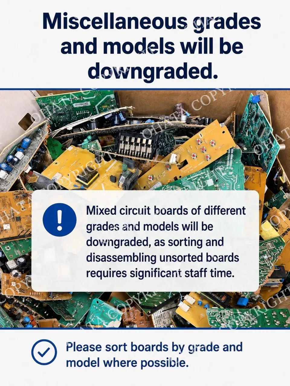
Mixed board categories may require separate inspection, sorting, weighing, and pricing. A mixed group should not be assumed to receive one uniform price.
Market prices can change according to copper and precious-metal markets, refining and processing costs, material quality, supply, demand, and current purchasing requirements. The applicable buying page should be checked before sorting or selling material.
Final classification, acceptance, and purchasing value are confirmed after inspection under current buying requirements.
Recycling, Data Security, and Classification Statement
HDD controller boards contain recoverable copper within their PCB layers, traces, ground planes, power pathways, contacts, and plated connections. Tin is commonly associated with solder, while nickel may be present beneath connector finishes or within other structures.
Selected contacts may have a thin gold finish for corrosion resistance and reliable electrical performance. Silver, palladium, aluminum, steel, silicon-based semiconductor material, fiberglass, resin, and other substances may also be present depending on the board and component construction. Exact material quantities vary by manufacturer, model, production period, and supplier. A photograph cannot establish internal copper weight, plating thickness, solder composition, or precious-metal content.
One large chip or gold-colored connector does not determine recycling value. The complete construction, component population, retained contacts, condition, contamination, and required processing must be considered. A typical professional recycling process may include collection, secure data handling, removal of the controller PCB, classification, condition inspection, material sorting, mechanical preparation, metal separation, and controlled refining.
Recovering usable metals reduces landfill disposal, supports the reuse of existing resources, and decreases some of the demand for newly mined material. Proper classification also improves inventory control, processing consistency, and separation of materially different boards.
User documents and other personal files are normally stored magnetically on the platters inside the hard-drive enclosure. A loose controller board generally does not contain these files, although it may contain firmware and calibration information. Removing the controller PCB is not a reliable method of erasing the data stored on the platters. Complete drives should undergo an appropriate data-destruction process when confidential information is involved.
The Ohata HDD Board Classification is an independent educational, purchasing, inventory, and recycling system developed from operational experience. It is not an international standard, government specification, ISO classification, storage-performance rating, or universally accepted electronic-scrap grade.
Its two broad groups support initial identification, but current purchasing requirements may establish more specific categories according to manufacturer, interface, form factor, production period, construction, components, completeness, condition, and recoverable-material profile.