

How to Read Motherboard and PCB Markings | Scrap Identification & Recycling Guide
Motherboards and other printed circuit boards are covered with letters, numbers, symbols, logos, stickers, and short codes. Some identify the board itself. Others identify a component location, production revision, manufacturing lot, safety certification, connector function, or polarity. Reading these markings correctly can help with parts research, repair, inventory control, and electronic-scrap identification.
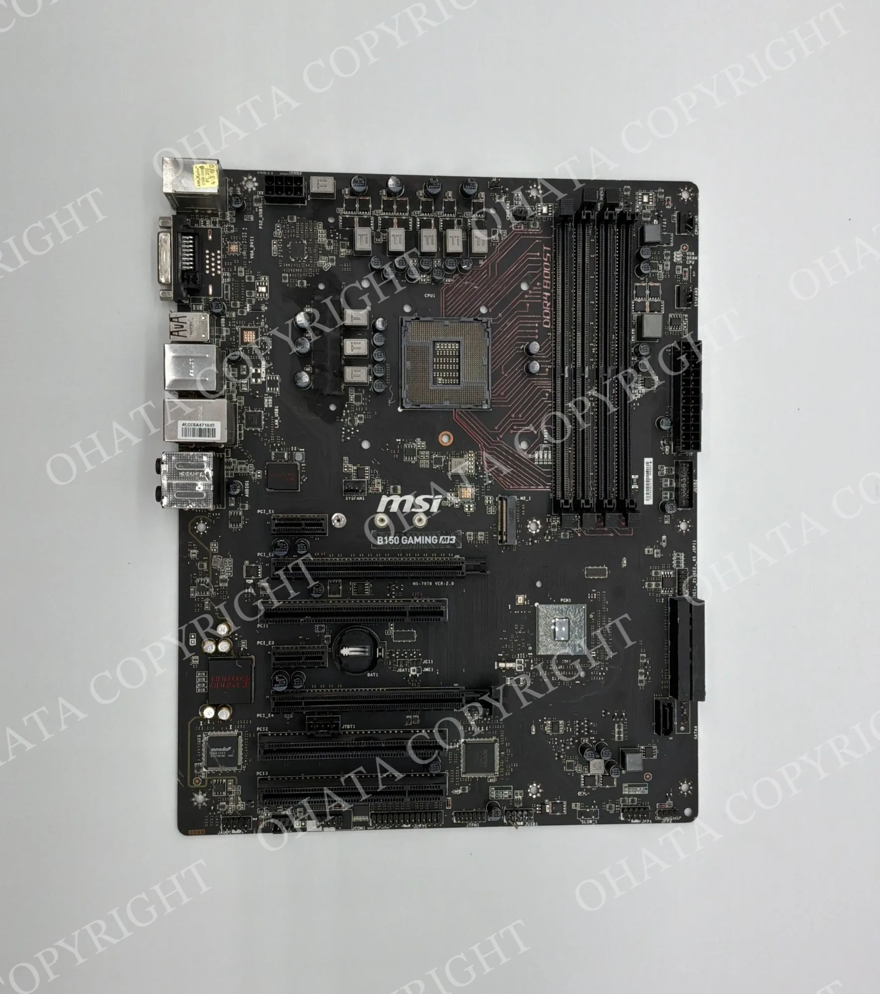
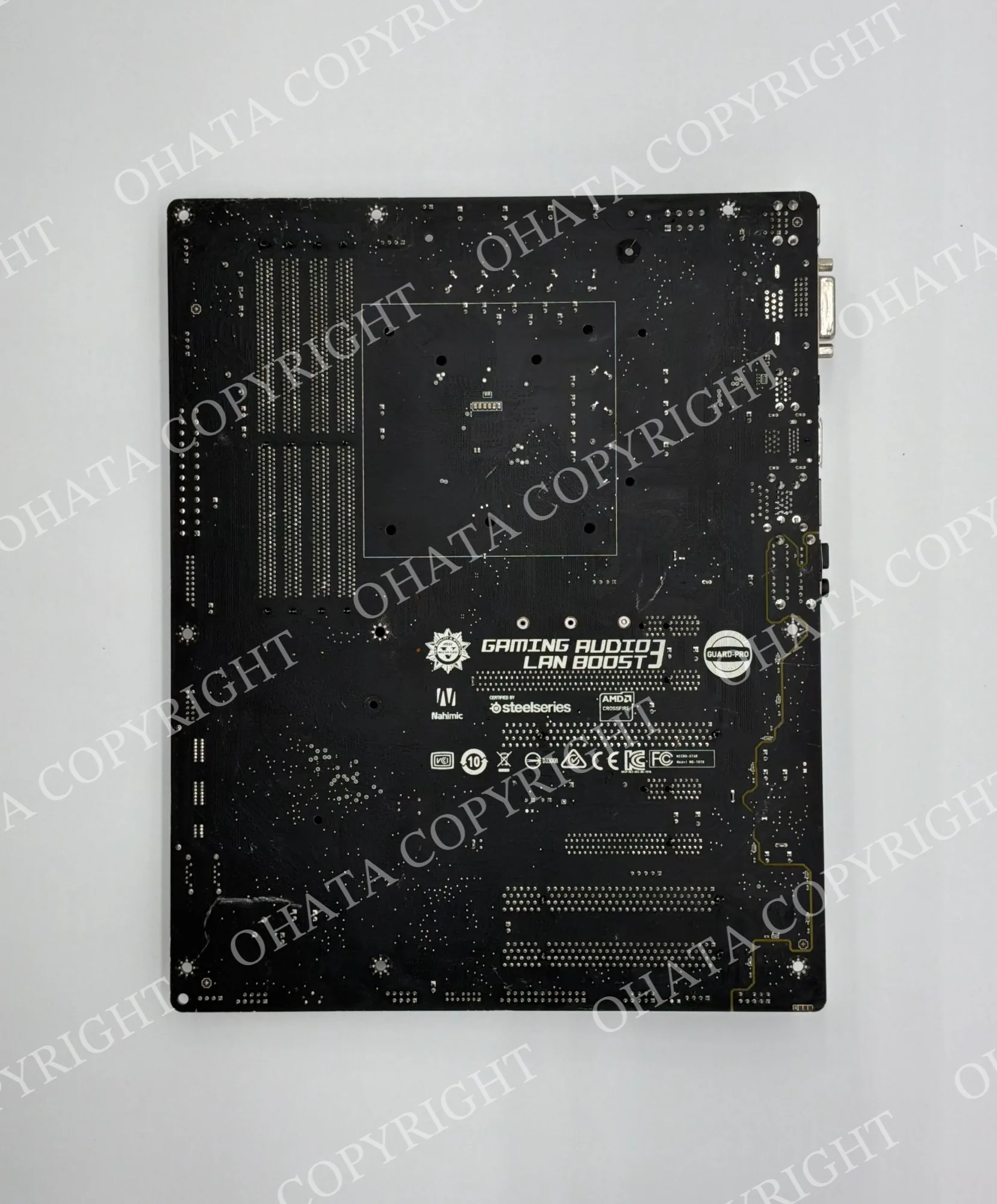
The most important rule is simple: not every visible code is a model number. A string beside a connector may describe the connector. A code beginning with E may be associated with a UL certification file. 94V-0 describes a flammability classification associated with the printed wiring board material or construction; it does not name the motherboard. A marking such as U17 identifies a component position in the design, not the part installed there.
Manufacturers use different numbering systems, and the same board may carry separate bare-PCB, assembled-board, service-part, serial, revision, and production identifiers. For recycling, markings should be combined with physical inspection of the complete board, its application, connector quality, component density, processor configuration, condition, and attached materials.
Why a single board can have many numbers
A motherboard passes through several stages before it reaches a computer or industrial machine. The printed board fabricator produces the laminated board with copper traces, holes, pads, solder mask, and permanent legend. An assembly company then installs components. An original equipment manufacturer may add a service label, barcode, serial number, or inventory identifier. Repair centers and equipment owners may later add asset tags or inspection stickers.
As a result, different markings can refer to different objects:
A bare-PCB number identifies the unpopulated printed circuit board design.
An assembly part number identifies the populated board as a finished subassembly.
A service or spare number identifies the replacement part used in an equipment maker's support system.
A revision code identifies a design or manufacturing change.
A serial number identifies one individual board.
A lot or date code supports production traceability.
A reference designator identifies one component position, such as
R125orU7.A certification or material mark describes compliance, recognition, or a tested property rather than the board model.
The exact relationship between these codes is manufacturer-specific. Two boards may share the same bare-PCB number but have different installed components and assembly numbers. Conversely, a service system may use one spare number for several compatible revisions. This is why a reliable identification should record more than one marking whenever possible.
Where markings appear
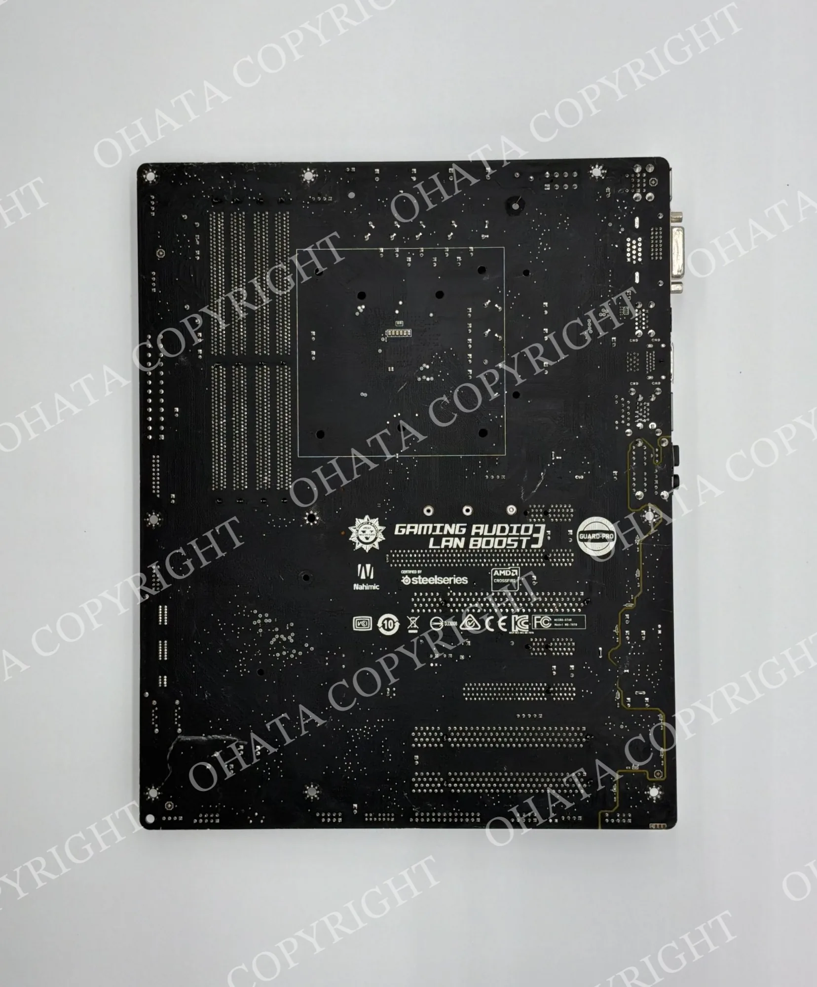
Look on both sides of the board. Identity numbers are often printed near an edge, memory slot, CPU socket, rear connector area, or barcode label. Revision information may appear beside the main board number. Reference designators are usually printed beside their components. Very small regulatory or laminate marks may appear on the reverse side where there is more open space.
Markings may be applied in several ways:
Silkscreen or legend ink: usually white, yellow, or black text printed over the solder mask.
Copper or solder-mask artwork: characters formed as part of the PCB layer artwork and therefore difficult to remove.
Adhesive label: commonly used for serial numbers, barcodes, service parts, and production tracking.
Laser marking: often used on IC packages, metal shields, or high-density labels.
Ink stamp or inspection mark: may indicate a factory, line, test, or quality-control step.
A damaged or missing sticker does not necessarily make the board unidentifiable. Permanent legend, connector layout, chipset markings, and other physical features may still narrow the search. However, a sticker alone should not be trusted if it appears to belong to a chassis, cable, or another removable part.
How markings relate to recycling value
Markings can help identify the source and likely application of a board. A confirmed server, telecom, industrial-control, laptop, desktop, hard-drive, or appliance application can guide the sorter toward the correct comparison group. Markings may also help separate revisions or document homogeneous lots.
They do not directly measure recoverable gold, silver, palladium, or copper. They also do not prove that all original components remain installed. A high-value model number printed on a stripped, burned, broken, or heavily contaminated board does not restore the value of the missing material. Physical construction and condition remain essential.
How to Identify a Board Based on the Markings
When several codes are present, begin with the largest or most prominent identifiers and look for labels.
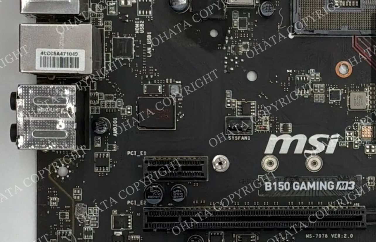
Use the following reading order:
Manufacturer or brand: Record the name or logo, but remember that the PCB fabricator, board designer, and final equipment brand may be different companies.
Model or board name: This is often the best first search term when it is explicitly labeled.
Assembly part number: Prefer a code marked
ASSY,ASM, or a brand-specific service identifier when researching the populated replacement board.PCB or bare-board number: Useful for tracing the underlying layout, but it may cover multiple assembled configurations.
Revision: Record it exactly, including punctuation and suffixes.
Serial, barcode, and lot data: Useful for traceability, but normally poor public search terms because they may be unique to one unit.
Never discard hyphens, spaces, leading zeroes, or suffix letters during transcription. REV A, REV A1, and REV 1.0 may describe different revision systems. A final -A, /B, or .02 can materially change the identity.
Part number versus serial number
A part number usually identifies a design or orderable item shared by many boards.
A serial number usually identifies one individual unit.
If two identical boards have the same printed code but different barcode strings, the shared code is more likely to be a part or assembly number, while the changing strings are more likely serial or lot identifiers.
Common clues include:
P/N,PN,PART,ASSY,ASM,FRU, andSPAREgenerally point toward a part or service identity.
S/N,SN,SER, andSERIALgenerally point toward an individual unit.
REV,VER,VERSION,EC, or an appended letter commonly indicates a revision or engineering-change level.
LOT,BATCH,DATE,D/C, and compact week codes usually support production traceability.
These are conventions, not universal rules. Always compare the code with manufacturer documentation or several confirmed examples.
Common PCB reference designators
Reference designators correlate physical components with schematics, parts lists, and service instructions. Manufacturers may use house conventions, so the letters below are common meanings rather than a universal decoder for every board.
Marking
Common meaning
What it usually identifies
RResistor
Fixed resistor or resistor network position
CCapacitor
Ceramic, film, polymer, or electrolytic capacitor position
LInductor
Coil or power inductor position
FBFerrite bead
Noise-suppression component position
DDiode
Rectifier, signal diode, TVS diode, or LED position
LEDLight-emitting diode
Indicator or illumination LED position
QTransistor
MOSFET, bipolar transistor, or other discrete transistor position
UIntegrated circuit
Controller, memory, logic, regulator, chipset, or other IC position
ICIntegrated circuit
Alternative to
Uused by some manufacturers
JJack or connector
Board connector, header, socket, or jack position
PPlug or connector
Plug, header, or connector position; usage varies
CNConnector
Connector position used by many manufacturers
FFuse
Replaceable or soldered fuse position
SWSwitch
Pushbutton, slide switch, DIP switch, or other switch position
TPTest point
Factory or service measurement point
YorXCrystal or oscillator
Timing crystal, resonator, or oscillator position
TTransformer
Transformer position; may have other house meanings
RTorTHThermistor
Temperature-sensitive resistor position
RVorVRVariable resistor
Trimmer or potentiometer position;
VRmay also mean voltage regulator in some designs
JPJumper
Configuration link, solder bridge, or jumper header
BATorBTBattery
Coin cell, backup battery, or battery connector position
MHorHMounting hole or hardware
Mechanical rather than electronic position
The number makes the location unique. For example, R104 means the resistor assigned designator 104; it does not mean 104 ohms. C12 does not state the capacitance. U7 does not identify the chip model. To identify the installed component, read the top marking on the component itself or consult the board's parts documentation.
Empty component outlines and population codes
A printed outline with a designator but no installed part does not automatically indicate damage. Manufacturers often use one PCB layout for several product configurations. Optional circuits may be left unpopulated at the factory.
Labels such as DNP, DNI, NP, N/F, NC, or NO FIT can mean “do not populate,” “do not install,” or “not fitted,” depending on the manufacturer's documentation. NC can also mean “no connection” in a schematic, so context matters. An empty location should be compared with clear factory examples before it is treated as a removed component.
Connector and slot labels
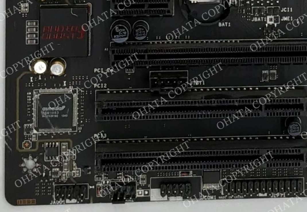
Functional labels identify interfaces rather than board models. Examples include CPU_FAN, SYS_FAN, DIMM_A1, SATA1, M2_1, PCIEX16, USB, F_PANEL, JTAG, COM, AUDIO, LAN, DC_IN, and ATX_PWR.
These labels are useful clues. They can help distinguish a memory slot from an expansion slot, identify a storage interface, or show where a fan, front panel, battery, or power cable connects. Slot numbering can also reveal channel order or installation priority. However, the same functional label appears on many unrelated boards and should not be used as the sole model identifier.
Polarity, orientation, and pin-one marks
Orientation marks prevent polarized components and connectors from being installed backward. Common indicators include:
A
+sign beside the positive pad of a polarized capacitor or battery connection.A bar or band associated with a diode's cathode side.
A dot, triangle, chamfer, notch, or numeral
1marking pin one of an IC or connector.A keyed outline showing the correct connector orientation.
A square pad used for pin one on some through-hole footprints.
Do not assume every stripe means the same polarity. For example, the stripe on many aluminum electrolytic capacitor cans marks the negative lead, while some tantalum capacitor markings indicate the positive terminal. The board legend, component datasheet, and package convention must be considered together.
Chip top markings
The characters printed or laser-marked on an IC package may include a manufacturer logo, complete orderable part number, shortened device code, package or temperature suffix, speed grade, mask or stepping code, assembly site, lot code, and manufacturing date.
Large packages often have enough room for a recognizable part number. Tiny SMD packages may carry only a two- to six-character top code. A short code is not globally unique; different manufacturers can reuse the same characters for unrelated devices. Identification therefore requires the manufacturer logo, package shape, pin count, surrounding circuit, and an official marking guide or datasheet.
Date formats are also manufacturer-specific. YYWW commonly means a two-digit year followed by the production week, and some device makers add internal trace characters. Microchip, for example, documents a YYWWNNN trace-code pattern for a particular device family, where YY is the year, WW is the week, and NNN is an internal code. That example should not be treated as proof that every chip or PCB uses the same format.
Understanding UL and PCB Safety Markings
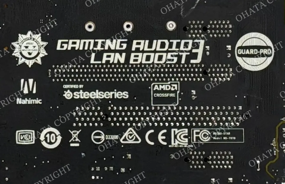
Marks such as the UL Recognized Component symbol, an
Enumber, and94V-0are frequently mistaken for motherboard model numbers.
An
Enumber can identify a company or certification file in UL's system. It may relate to the printed-board fabricator or a recognized material or process, not the final computer brand.
94V-0refers to a vertical-burning flammability classification under UL 94. It is not a quality grade, layer count, date, model number, or indication of precious-metal content.A string beside those marks may be a laminate, factory, or printed-wiring-board type designation.
The safest method is to search the complete E number in UL Product iQ and compare the returned company and category with the board. Do not identify a motherboard solely from the company named in that certification record.
RoHS, lead-free, CE, FCC, and WEEE symbols
Environmental and regulatory marks describe requirements or declarations, not scrap grades.
RoHS,Pb-free,LF, or a crossed-outPbsymbol may indicate a lead-free or restricted-substances manufacturing program. They do not prove that every solder joint or replacement component has the same composition.The crossed-out wheeled-bin WEEE symbol means the electrical or electronic product should be separately collected rather than discarded as unsorted waste. The European Commission's WEEE guidance notes that a bar beneath the bin can indicate equipment placed on the market after August 13, 2005; it is not a general PCB manufacturing-date code.
CE,FCC, and similar marks generally concern the product or equipment's regulatory status. Their presence on a board does not identify its component density, precious-metal yield, or Ohata grade.
Board dates, copyright years, and lot codes
A four-digit code such as 2318 might mean week 18 of 2023, but it might also be an internal drawing, lot, or option code. Confirm a date interpretation only when the manufacturer uses a known format or when several consistent clues support it.
A copyright year in the artwork usually indicates when the design or intellectual property notice was created. It does not necessarily equal the board's assembly date, the equipment's sale date, or the date of the final revision. Likewise, component date codes can predate board assembly because parts may remain in inventory before use. A code that appears to postdate the equipment by many years may belong to a repaired or replaced component.
Barcodes, QR codes, and 2D Data Matrix codes
Machine-readable labels often encode a part number, serial number, work order, factory, or lot. The human-readable text printed beside the symbol is usually the safer first record. Scanning can help, but a decoded string still needs interpretation. A barcode does not automatically represent the retail model, and a QR code may lead only to an internal manufacturing system that is unavailable to the public.
For inventory, photograph the entire label before removing dust or attachments. Keep leading zeroes and distinguish easily confused characters such as 0/O, 1/I, 5/S, 8/B, and 2/Z. Intel's product-marking guidance specifically warns that similar letters and numerals can be misread when recording product markings.
Recommended Order of Checking
Use a consistent process instead of searching every visible number:
Examine both sides of the board and locate the largest permanent markings and attached identification labels.
Look for terms such as
MODEL,P/N,PART NO.,ASSY,PCB,BOARD,REV,VER,FRU, orSPARE.Record the model, part number, board number, and revision exactly, preserving hyphens, spaces, leading zeroes, and suffix letters.
Separate board-level identifiers from reference designators, serial numbers, date or lot codes, compliance symbols, connector labels, and component top markings.
Search the most specific shared identifier in quotation marks. Begin with the model, assembly number, service part number, or permanent PCB number rather than a unique serial number.
Compare possible matches with the board’s shape, mounting holes, processor configuration, memory slots, expansion slots, connector placement, and major chipset markings.
Record any uncertainty. If the evidence supports multiple models, revisions, or applications, do not force an exact identification.
Photographs are optional when the board is physically available. They are useful for enlarging very small markings, documenting a recycling lot, preserving identification details, or requesting assistance from a buyer or technician.
Never power unknown scrap hardware solely to identify it. Inspect the board while it is disconnected and follow appropriate electrostatic-discharge and workplace-safety procedures.
Buying, Downgrade, and Rejection Guidance
BGA material should be clean, dry, identifiable, and reasonably complete. Keep loose devices separate from circuit boards, batteries, heatsinks, fans, steel hardware, and packaging waste. When requesting an evaluation, provide clear photographs of the top markings and underside.
Material may be downgraded for:
Mixed or unidentified devices
Missing solder balls or removed dies
Cracked packages or damaged substrates
Corrosion, burned residue, or heavy thermal compound
Attached hardware or other contamination
Wet, chemically treated, hazardous, deliberately misrepresented, or heavily processed material may be rejected. Store loose devices in clean, dry, labeled containers, separating intact material from damaged or uncertain pieces.
Under the Ohata Board Scrap Classification System, each complete PCB is evaluated according to its application, construction, component density, connector quality, completeness, cleanliness, and condition. Printed markings can support identification, but no model number, revision code, certification symbol, or component label determines the PCB grade by itself.
Ohata.ai Vision 1.0 may assist with preliminary identification from photographs. Final acceptance, classification, and buying price are determined after physical inspection and may depend on the material type, condition, completeness, quantity, and current buying standards.